
ART2955S ART150
Common power transformers have two windings
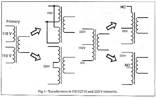
One winding is the high-voltage primary to be connected to the power grid and may have a tap or be formed by two different windings, as shown in Figure 1.
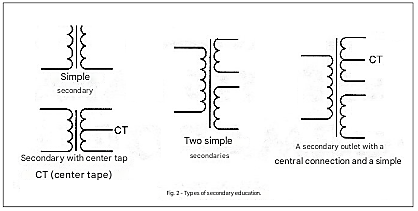
The other winding is the low-voltage secondary winding, which can be single, double, or have branches or taps, as shown in Figure 2.
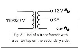
In the normal application of these components, we apply alternating voltage to the input or primary winding, according to its value, and take the desired (nominal) voltage from the secondary winding, according to the winding or tap, as shown in Figure 3.
However, what many don't know is that we can manipulate the characteristics of the two windings and the taps themselves, thus obtaining behaviors different from the norm, leading to some differentiated applications for this type of component.
Let's analyze some of them.
a) Autotransformer
The primary winding of a common transformer with a tap allows its use as a step-up or step-down autotransformer. Thus, a transformer with a 110/220 V winding, as shown in Figure 3, can be used to lower the mains voltage from 220 V to 110 V or to increase the mains voltage from 110 V to 220 V.
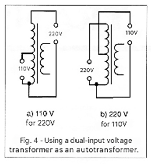
In Figure 4(a) we have the first case where we use the transformer to lower the mains voltage from 220 V, noting that there is no isolation from the mains to the load and that the secondary, regardless of voltage, remains disconnected. In Figure 4(b) we have its use as a voltage booster, and in this case, we also note that there is no isolation from the mains and that the secondary remains disconnected.
The maximum power that the transformer can handle in this type of application is small. Thus, if we have a transformer with a 12 V x 1 A secondary representing a 12 W load, the maximum load for the circuit powered by the transformer in the application will be of the same order. Otherwise, it may overheat and burn out. This means that the use of a small power transformer in this application is limited to very low power applications.
b) Small Voltage Step Regulator
A transformer with a low-voltage secondary between 6 and 12 Volts can also be used to add or subtract this voltage from the mains voltage.
This leads us to an interesting application: acting as a compensator for power grids that have voltage above or below normal, causing malfunctions in appliances. The first case is shown in Figure 5, where we use a 6 to 12 Volt transformer to add this voltage to the mains voltage.
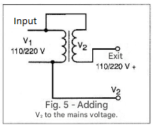
If the power grid has an abnormally low voltage, 95 volts for example, we can add 12 or 15 V from a transformer, obtaining 107 to 110 V, by connecting the transformer as indicated. The second case is shown in Figure 6 where the secondary voltage is subtracted from the grid voltage. Thus, in a grid where we have around 130 V, which can strain certain equipment, we can subtract 12 or 15 V from a transformer and thereby obtain a lower voltage for the load.
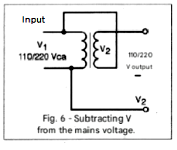
The maximum power that can be supplied to a load is given by the current in the transformer's secondary winding. For example, for a 1 A secondary winding (regardless of voltage), a current of 1 A in a 110 V network corresponds to a maximum load of 110 W, and in a 220 V network, 220 W. An interesting practical circuit is shown in Figure 7, which shows a manual voltage regulator with two 12 V steps.
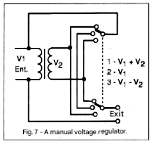
With this circuit we can add 12 V to the output voltage relative to the mains voltage, maintain the mains voltage, or subtract 12 V from the mains voltage. We can say that it is a regulator with 3 positions:
1. Subtracts 12 V
2. Maintains the mains voltage
3. Adds 12 V
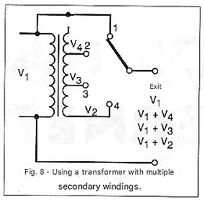
If the reader can obtain a power transformer with multiple secondary voltages, as shown in Figure 8, they can design a regulator with more positions.
c) Transformer Connections
Another important application of transformers is through the connection of several units. Thus, we can connect the primary windings of the transformers in parallel to the power grid, supplying them in the conventional way. However, the secondary windings that will be connected in series can be placed in phase or in opposite phase, which leads to two possibilities. The first is shown in Figure 9, where we have the sum of the voltages.
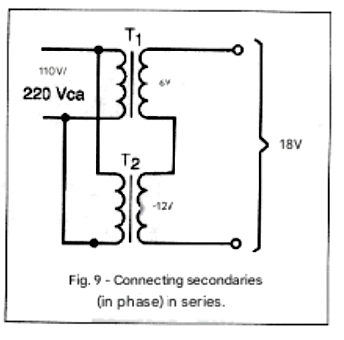
In this case, if we use a 12 V transformer in series with a 6 V transformer, we can obtain 18 V. The maximum current will be the current of the winding with the lower capacity. For example, if we use a 6 V x 1 A transformer and a 12 V x 500 mA transformer, the maximum current obtained will be 500 mA. The second scenario is shown in Figure 10, where the windings are in opposite phase. In this case, the voltage obtained will be the difference between the voltages of the associated windings.
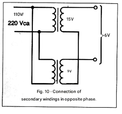
Similarly to the previous case, the maximum current will be the current of the winding with the lowest capacity. This type of reasoning applies to the connection of windings from more than two transformers. The transformers used have 6V and 15V windings, both with 500mA.
d) Isolation with two transformers
Figure 11 shows an interesting application that allows us to improvise an isolation transformer with two identical common transformers of any secondary voltage.
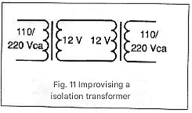
In this case, the first transformer lowers the mains voltage to a predetermined value, which is then increased by the next transformer, returning to the original voltage. The maximum power this circuit should operate at is the power of the transformers, compensating for a certain loss that exists in the two successive energy transformations.
CONCLUSION
The phase of the windings can be verified both with an oscilloscope and by the series connection itself. Series windings can have their voltages added or subtracted, and this can be verified with a simple multimeter. The different applications we have seen are just a few of others that imaginative readers can discover. If you have any other interesting applications to suggest, write to us and we will be happy to publish them after analyzing their feasibility. In any case, in all applications involving the use of transformers, always keep in mind that there are losses in the transformation, therefore the power obtained at the output is less than that applied at the input.


