
ART1380S ART2358
(*) The article is from 1988 when there were few options for low-cost solar cells. Today they are common and any equivalent can be used in this project.
The idea is extremely simple: the solar cell is connected directly to a highly sensitive reed relay so that it is activated by the incidence of light. With the activation of the reed relay, various systems can be activated or deactivated, including the power supply of intermediate power control systems.
There are many possible practical applications for such a system, such as:
• Automatic lighting systems for streets, squares, gardens, shop windows, etc.
• Solar energy harnessing systems;
• Light alarms.
No component of the assembly is critical, and some wiring suggestions for control will be given throughout the article.
HOW IT WORKS
The circuit is based on a 1.8-volt Heliodynamic solar cell, whose maximum (short-circuit) current reaches 500 mA under intense sunlight.
This cell is directly connected to a reed relay, as shown in Figure 1.
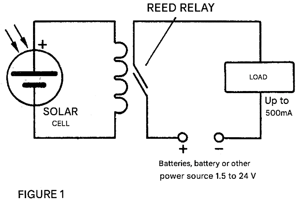
We can then use this reed relay to switch the desired device on or off, and if its power is higher, to switch an intermediate circuit on or off. The only precaution in designing the project is choosing the reed relay. For this, we have several possibilities, since we can use anything from a commercial type to "making one" from a common reed switch.
This relay would be "made" by winding 300 to 500 volts of 28 or 30-gauge wire around its bulb, as shown in Figure 2.
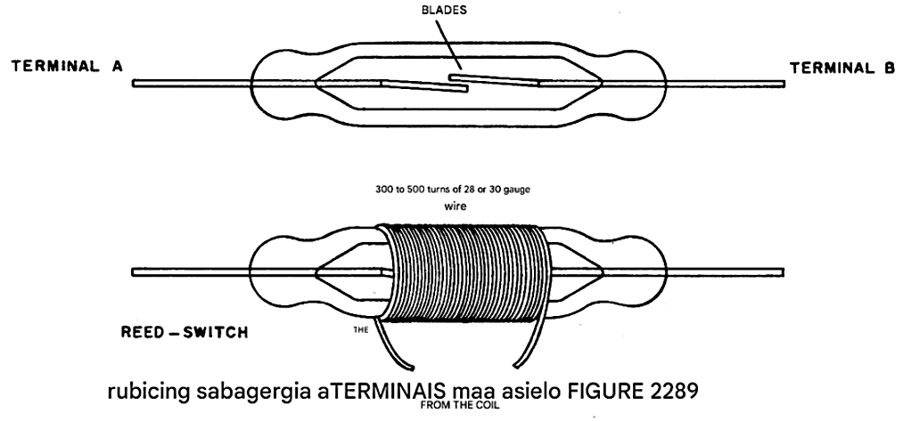
The ideal number of turns depends on the sensitivity of the reed switch, which is determined by the flexibility of its blades. Both normally closed and normally open types can be used, depending on the desired load control.
CIRCUITS
The simplest control circuit for a load according to the current capacity of the reed switch (usually no more than 500 mA) is shown in Figure 3.
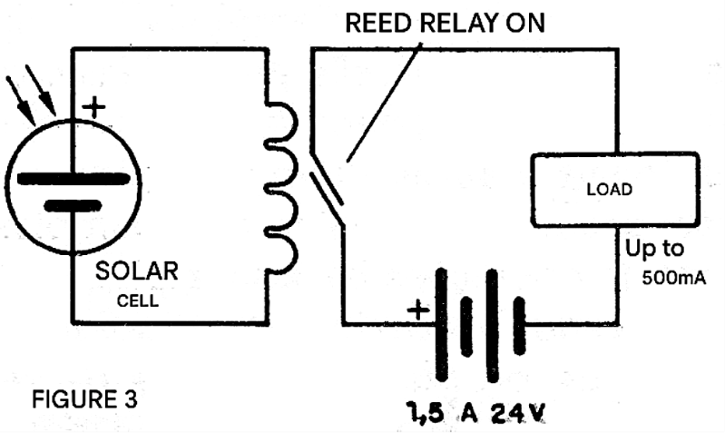
The connecting wire to the solar cell should not be long (maximum 5 meters), as its resistance can affect the transferred energy and thus cause triggering problems. The circuit shown in Figure 3, using a reed switch with normally closed contacts, activates the load when light falls on the solar cell.
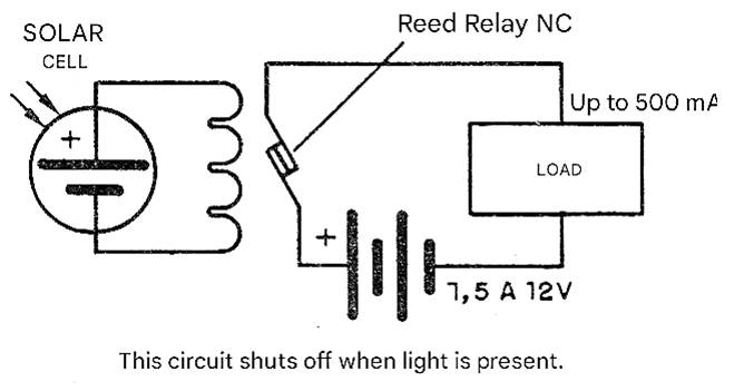
To disconnect the load, the indicated circuit would use a normally closed reed switch, as shown in Figure 4.
The circuit in Figure 5 is for activating an intermediate load for higher power control.
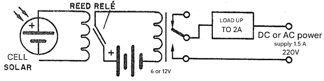
In this case, batteries or a power supply of 6 or 12 V are used, in which case the relays employed are of the type that can control up to 2 A of current. The excitation current of the coil of these relays is below the maximum allowed by the reed-switch contacts.
Note that, in this case, the reed-switch can be of the NO type and the relay can have its contacts either NO or NC used to control the load. In fact, a pair of contacts can even be used for a monitoring system with common LEDs, if energy consumption is not an important factor in the application.
In Figure 6 we have a circuit where, instead of a relay, we use an SCR. The SCR must be of a type that has a trigger voltage according to what can be supplied by the cell.
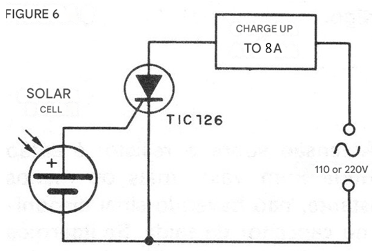
Typically, the trigger voltages of SCRs and Triacs are between 0.8 and 2.0 volts, which means that if we have a "harder" trigger type within a batch, requiring a voltage of 1.6 V, for example, there may be a triggering problem.
It is advisable to experiment in this case. For the Texas Instruments TIC126, which has a maximum control current of 8 A, the trigger current varies between 5 and 20 mA, which is within what the cell can easily supply. The TIC126 can be found with suffixes indicating its operating voltage. These are:
F = 50 V
A = 100 V
B = 200 V
C = 300 V
D = 400 V
E = 500 V
M = 600 V
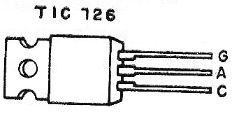
The SCR must be equipped with a heat sink when controlling loads with high currents. Note that this circuit has zero quiescent current, since in the non-conducting condition the resistance between the two main elements of the SCR can be considered infinite. The terminals of this component are identified in Figure 7.
We also remind you that the wire connecting to the cell must be limited in length to prevent losses.


