
ART745S ART2238
A sudden spike in current often signals an abnormality in a system. In some scenarios, a simple warning is enough to allow for manual intervention. In others, the system must be immediately shut down to prevent damage or hazardous conditions.
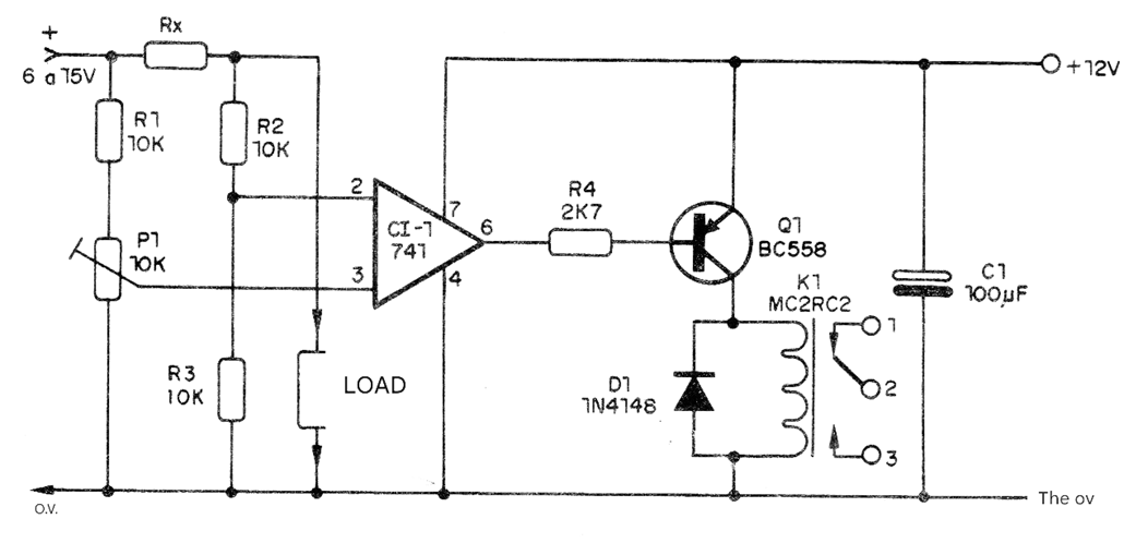
This sensor simplifies current monitoring. By using a sensing resistor (Rx) the circuit triggers a relay once the current reaches a pre-programmed value. It is versatile enough to handle currents ranging from a few milliamperes to tens of amperes, depending on the choice of Rx.
The circuit is very simple and can operate with currents ranging from a few milliamperes to tens of amperes, all depending on the value of resistor Rx. The circuit is powered by a 12V supply and can be taken from the equipment with which it will operate.
Characteristics:
• Supply voltage: 12V (or range of 9 to 18V)
• Relay contact current: 2A (double contact)
• Idle current: less than 10mA
• Triggering current: 1mA to 10A
HOW IT WORKS
An operational amplifier is connected as a voltage comparator, as shown in Figure 1.
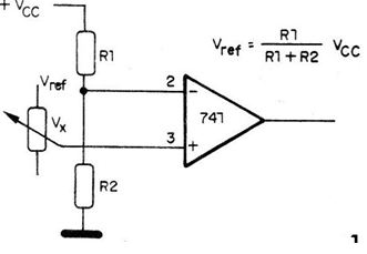
The output voltage will then be positive if the voltage at pin 2 is less than at pin 3, and negative if the voltage at pin 2 is greater than at pin 3.
When the voltage at both inputs has the same value, the output presents an intermediate value between 0 and the supply voltage, i.e., Vcc/2.
The voltage will be positive at the output if the voltage at the non-inverting input is greater than the voltage at the inverting input and negative if the voltage at the non-inverting input is less than that at the inverting input.
The operational amplifier amplifies the voltage difference, and since it has a gain of around 100,000 times, the transition at the output at the indicated points occurs very quickly, as shown in Figure 2.
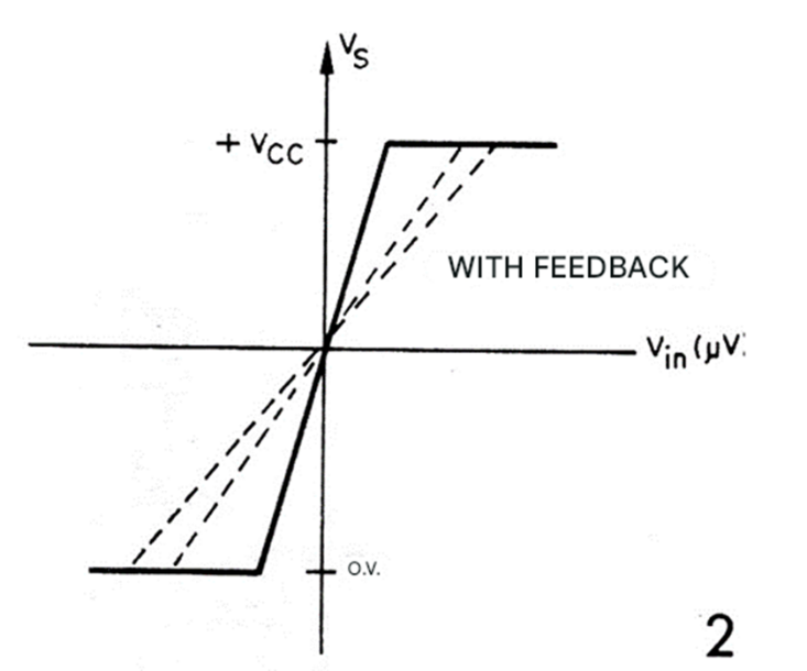
Thus, for a voltage difference of only 9 uV between the inputs, we have a variation in the output voltage of 0.9 V, which is sufficient to bias the transistor that excites the relay.
What we have to do then is dimension the resistor Rx so that we have the transition with the desired current, and adjust P1 to the trigger threshold.
In a simple way, we can give the value of Rx: 10 for 1 ampere, increasing its value in inverse proportion to the decrease in current.
This value allows a relatively easy adjustment of P1 for triggering at the ideal point.
One way to change the linearity of the integrated circuit's response, making it slower, is with feedback between the output and the inverting input, as shown in Figure 3.
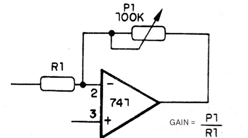
With a 100 k ohm potentiometer, we can change the trigger response curve, depending on the application, making the adjustment of P1 less critical.
Note that the voltage reference, being given by a resistive divider, allows the use of a single source instead of a symmetrical source, which simplifies the design.
The transistor used as a driver is a PNP 80558 or equivalent. Diode D1 serves to protect the transistor against the high voltages generated in the relay coil during switching.
ASSEMBLY
Figure 4 shows the complete sensor diagram.
Since these assemblies will generally be part of other projects, the board design can be added to their layouts, but Figure 5 shows an independent version that can be added to devices or circuits.
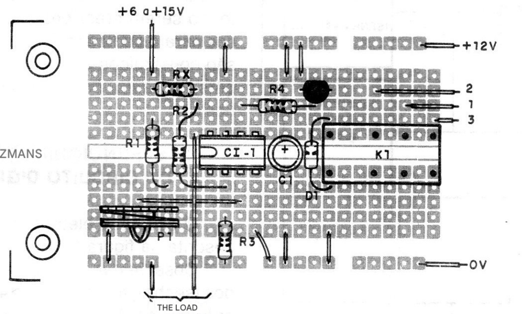
For the integrated circuit and the relay, we suggest using DIL sockets.
The resistors are all 1/8 or ¼ W with up to 20% tolerance; for greater precision, a multi-turn trimpot can be used. The cables or traces that carry the load current must be sized according to its intensity.
Note the common point of the negative power supply circuit. As for the transistor, any general-purpose PNP type with a collector current of at least 100 mA will work.
Occasionally, higher power transistors can be used, with the reduction of R4 to 1 k ohms for driving larger relays. Capacitor C1 must have an insulation voltage of 16 V or more, depending on the supply voltage. For D1, any general-purpose silicon diode will do, even rectifiers like the 1N4002.
TESTING AND USE
Turn on the unit and initially adjust P1 so that, with the normal current intensity in Rx, the circuit is about to trigger.
Then, increase the current in the load, checking if the triggering occurs as expected.
The value of Rx should be as low as possible to obtain a trigger with the desired current, as this will prevent voltage drops in the circuit.
Values in the range below 1 ohm are recommended, if possible.
If there is difficulty in adjusting the exact triggering point, place a 100 k ohm trimpot between the output and the inverting input of the integrated circuit (pin 2) to control its gain.
Bill of Materials (BOM)
IC-1 - 741 - operational amplifier
Q1 - BC558 - general purpose PNP transistor
D1 - 1N4148 - general purpose silicon diode
P1 - 10 k ohms - trimpot
K1 - 12 V micro-relay
Rx - see text
R1, R2, R3 - 10 k ohms - resistors (brown, black, orange)
R4 - 27 k ohms - resistor (red, violet, red)
C1 - 100 uF x 16 V - electrolytic capacitor
Miscellaneous: printed circuit board, DIL sockets for the relay and integrated circuit, wires, solder, etc.


