
ART740S ART2232
The ability to memorize a single pulse can be very useful in applications involving the installation of digital systems, alarms, sound systems, or even conventional electrical installations. The basic idea of the project we propose is a simple system that verifies whether the impulse caused by the activation of a switch, or even by the presence of a logic level at an output, propagates to the other end of a line, without needing someone on the other side to verify the fact.
If the command impulse reaches that point, it will be recorded by lighting an LED that can be checked after as much time as we want. The circuit is powered by 6V from 4 common batteries, and the impulse to be recorded must have an amplitude corresponding to values between 5 and 6 V. Since the circuit operates with an extremely low current, it can be used in many ways, practically without loading the circuit used for impulse transmission.
Among the possible practical applications, we highlight:
• Testing of data transmission lines.
• Testing of cables and various installations.
• Recording of equipment activation.
• Recording of location tampering.
HOW IT WORKS
The basis of our simple circuit is a single CMOS 4013 integrated circuit, which consists of a dual D-type flip-flop. Only one of the flip-flops is used, with an LED at output 0 that lights up when the logic level is high (1). When the device is turned on, we can easily reset it by simply pressing S1.
This same switch will also be used to reset the device if we want to repeat a test. Resistor R4, in series with the LED, serves as a current limiter.
The signal input is made through pin 3 via a network formed by two resistors and a capacitor. The purpose of the capacitor is to prevent triggering by transients or bounce action, in case the remote signal source, used to activate the device, is a common switch. The 4013 flip-flop changes state with the positive transition of the input logic level, which is maintained at zero by the presence of R2.
The current consumption of the integrated circuit at the power level is very low, only a few milliamperes, and when the LED is lit, this current does not exceed 20 mA, which guarantees excellent durability for the batteries used in the power supply.
ASSEMBLY
Figure 1 shows the complete diagram of our pulse register.
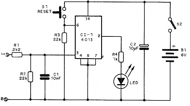
Figure 2 shows the component layout on a universal printed circuit board.
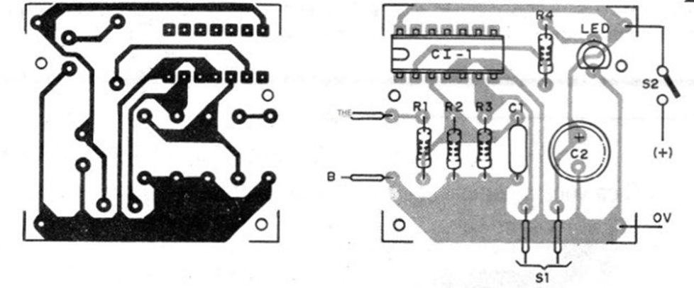
The entire assembly can be installed in a small plastic box that will use a pair of alligator clips or two screw terminals for the signal output. The resistors are 1/8 W with 10% and the capacitor Ct can be either ceramic or polyester.
The capacitor C2 is an electrolytic capacitor with a minimum working voltage, and the LED is a common red LED. For the integrated circuit, we suggest using a 14-pin DIL socket, and for the batteries, an appropriate holder should be used. The circuit can also operate with a 9 V battery.
TESTING AND USE
The test is immediate: by momentarily connecting input A to the (+) of the device's power supply, the LED should change from off to on. If, upon turning on the device, it lights up immediately, it should be reset by momentarily pressing S1. Figure 3 shows how to test a two-conductor line using a set of 4 small batteries as a signal source.
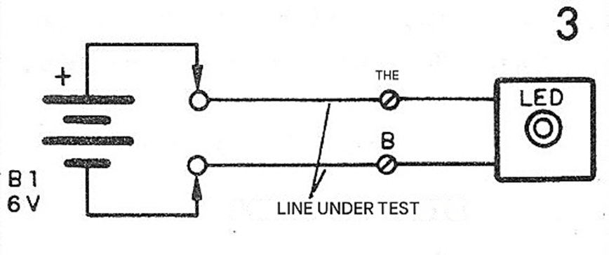
The momentary touch of the battery holder wires to the line should cause the LED to change from low to high, provided there are no interruptions in the cables. For testing logic circuits, the output itself can be used as a pulse source, connected to point A. Point B will be connected to the device's ground.
Parts List
IC-1 - 4013 - CMOS integrated circuit
LED1 - Common red LED
B1 – 6 V - 4 small batteries
S1 - Pushbutton switch
S2 - Simple switch
R1 - 2.2 k ohms x 1/8 W - resistor (red, red, red)
R2, R3 - 22 k ohms x 1/8 W – resistors (red, red, orange)
R4 - 1 k ohms x 1/8 W - resistor (brown, black, red)
C1 - 10 nF - ceramic capacitor
C2 - 10 uF x 6 V electrolytic capacitor
Miscellaneous: printed circuit board, battery holder, mounting box, input terminals, socket for the integrated circuit, wires, solder, etc.


