
ART1480S ART2253
Twin-T oscillators, when adjusted to produce damped oscillations, accurately mimic instruments such as drums, tambourines, and bongos. This article proposes a set of four oscillators operating at increasing frequencies to emulate a bongo kit with excellent performance.
The circuit is powered by standard batteries or a power supply (which can also power the amplifier). The design is straightforward, utilizing general-purpose transistors, while the amplifier section features an integrated circuit delivering approximately 1 W of power. Required adjustments are minimal, focusing only on the ideal oscillation point or tuning for each "bongo."
The main characteristics of this circuit are:
• Supply voltage: 9 to 12 V
• Number of oscillators: 4
• Current consumption of the multiple-oscillator: 2 to 3 mA
• Activation type: touch
THE CIRCUIT
Figure 1 shows the positive feedback network that determines the operating frequency.
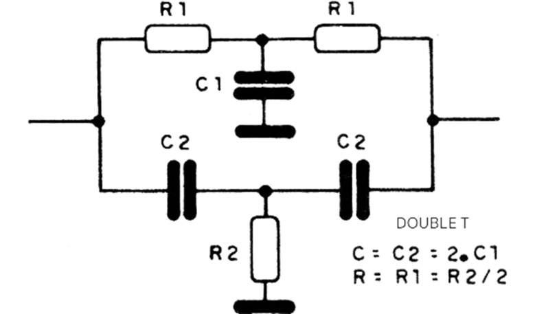
This frequency depends on the values of the resistors and capacitors, which must maintain a defined relationship, given next to the diagram itself:
f: 1/(2 x 3.14 x R x C)
where:
3.14 is π
f is the frequency, in Hz
R is the resistor value, in ohms (With R = R1 = R2/2)
C is the capacitor value, in Farads (with C = 2 C1 = 2 x 2)
In an oscillator with appropriate feedback, the amplitude of the oscillations remains constant, and we have a continuous oscillation.
However, if the feedback is insufficient to maintain the oscillations, what we have is the production of damped oscillations, that is, oscillations whose amplitude decreases over time, as shown in Figure 2.
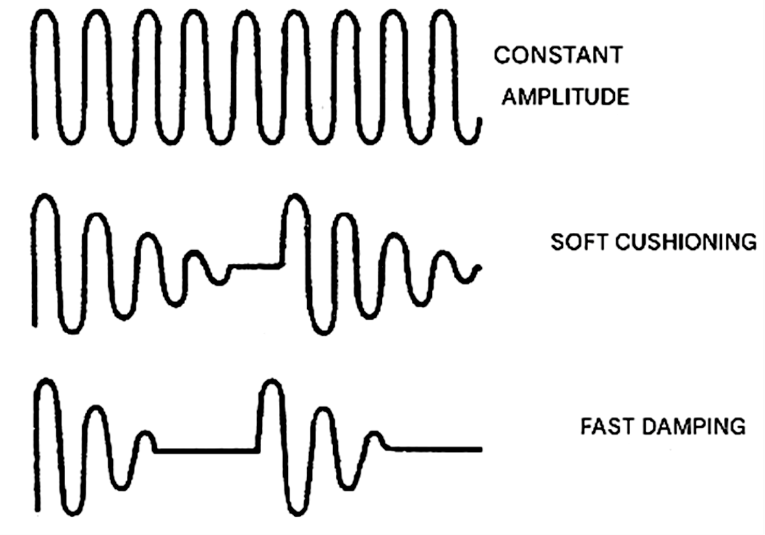
Depending on the damp, we have the imitation of various types of percussion.
Long damping imitates the metallic sound obtained when striking a piece of iron, glass, or even a bell. Fast damping imitates a sharp hit, like that obtained when two blocks of wood collide with each other.
By adjusting the feedback with a trimpot at the appropriate point, we can obtain the timbres that characterize these instruments. In our case, since we want the sound of bongos, which represents a sharp hit with a prolongation that is not quite metallic, we will have an intermediate setting, with medium damping.
In our project we have four double-T oscillators, whose frequencies increase on a scale that allows us to imitate bongos. Their outputs are mixed and fed to a single point, which can be connected to the input of an amplifier.
The signal level of around 1Vpp obtained, with an impedance greater than 10 kΩ, allows the assembly to be coupled to the input of any amplifier. The oscillator is driven in an interesting way.
Since we have damped oscillations, each oscillator does not start operating without external excitation. This excitation consists of mains noise, which is applied when we touch sensors coupled to the bases of the transistors via a double T.
The touch causes the excitation that produces the initial pulse and leads to the damped oscillations adjusted on each trimpot. For those who do not want to depend on an external amplifier, and thus make the instrument portable, we suggest using a simple integrated amplifier.
This amplifier uses a TBA820M (8-pin version of the TBA8208) that can be powered with voltages from 9 to 12 V. The good power and gain of this small amplifier should be matched with the use of a speaker that has good mid and low frequency response.
We suggest using a heavy speaker, at least 15 cm in diameter, so that the lower frequencies of the last oscillator are not lost or excessively attenuated. If only the oscillator assembly is used, without the amplifier, a 9V battery is sufficient to provide a fairly long operating time.
However, with the amplifier, which has a somewhat high current draw, common small or medium-sized batteries (6 units) should be used, or even a power supply with a capacity of at least 250 mA. Filtering this power supply is very important to avoid hum in the reproduction.
Figure 3 shows a suggested power supply.
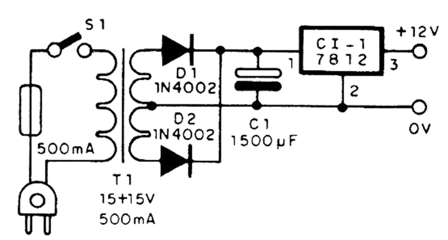
The transformer has a secondary of 12 + 12 V or 15 + 15 V (or intermediate values) with a current of 50 mA or more. The diodes in this power supply are type 1N4002 and the electrolytic capacitor is 150µF with an operating voltage of 16 V or more. The 7812 integrated circuit should be fitted with a small heat sink.
ASSEMBLY
Figure 4 shows the complete diagram of the four oscillators used in the basic bongo drum.
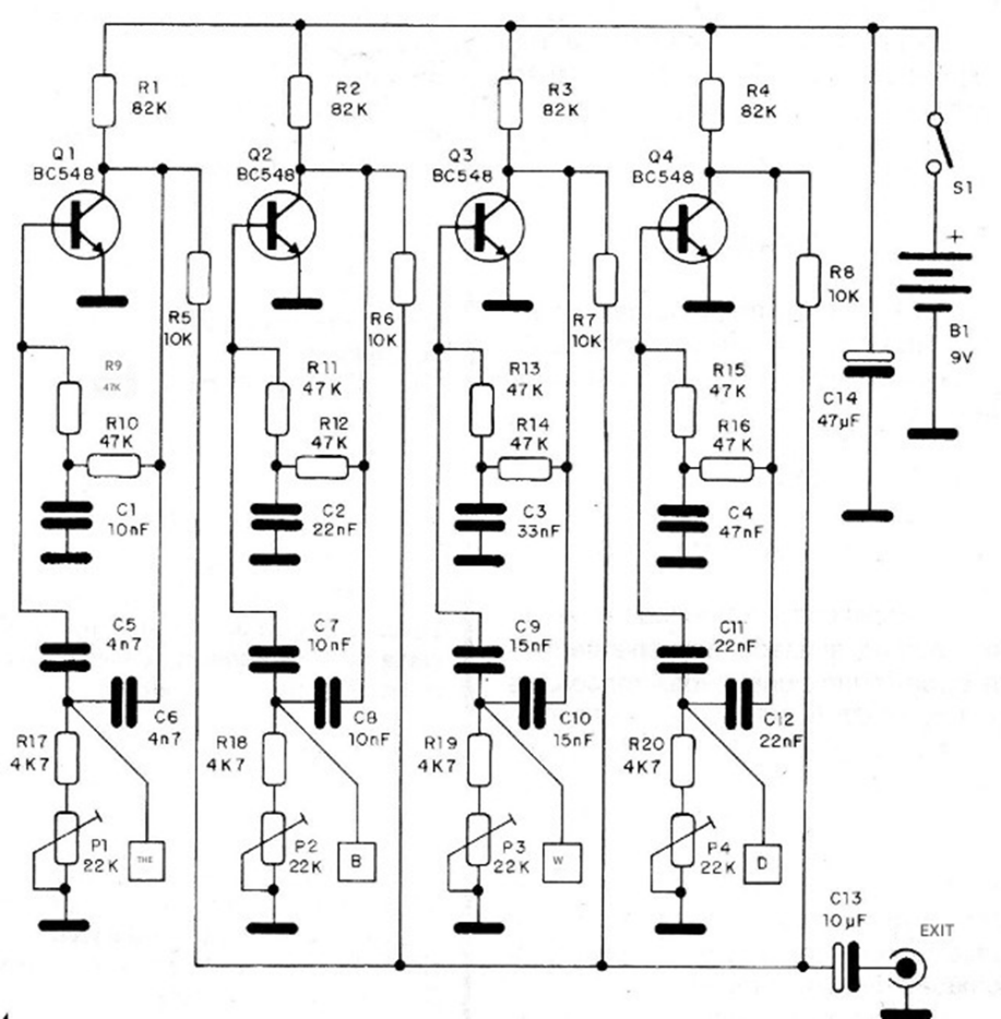
The assembly, based on a universal printed circuit board with a breadboard layout, is shown in Figure 5.
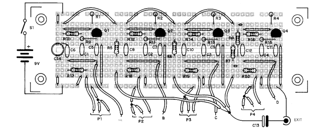
The touch actuators (A to D) consist of metal plates or even printed circuit boards connected to the indicated points. The transistors used are general-purpose NPN transistors, such as BC548 or equivalents such as BC237, 80238, BCS47, etc.
The resistors are all 1/8 or 1/4W, with 5 or 10% tolerance, and the capacitors can be either ceramic or polyester. The electrolytic capacitors must have a working voltage of 16V or more.
The trimpots are common, and the output cable to the jack must be shielded. An appropriate connector must be used for the battery, and the simple switch can be either a slider or a lever type. The assembly can be installed in a plastic box, as shown in Figure 6.
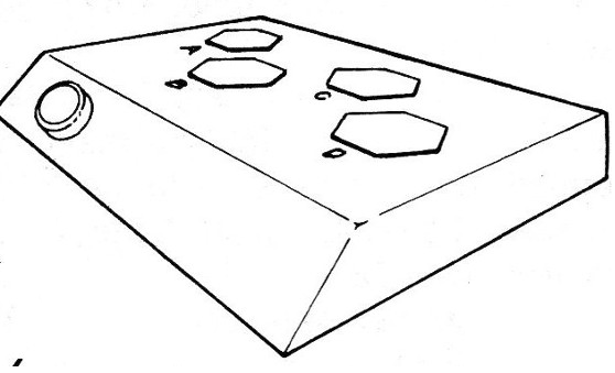
Figure 7 shows the diagram of the amplifier suggested for this project, including the volume control.
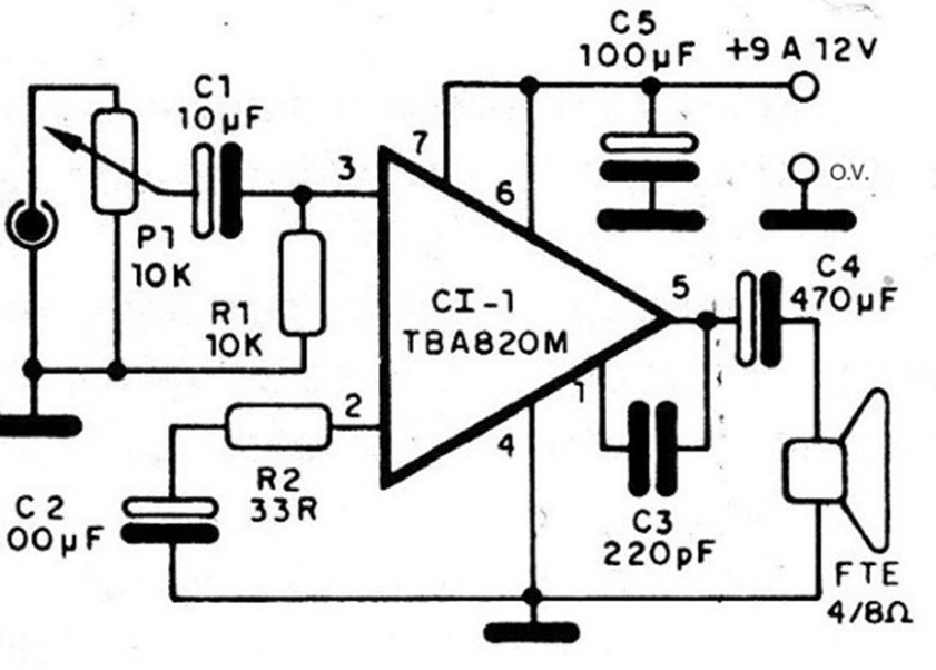
The speaker can be installed in a small acoustic enclosure or even a larger enclosure from commercial sound equipment can be used without problems. The resistors are all 1/8 or ¼ W, with 5 or 10% tolerance, and the electrolytic capacitors should have a working voltage of 16 V.
The volume control potentiometer should be 10 oz and, optionally, a master switch can be included. For the integrated circuit, we suggest using an 8-pin DIL holder, which will facilitate its replacement if necessary and avoid heat problems that can occur during the soldering process.
Note that the input cable must be shielded.
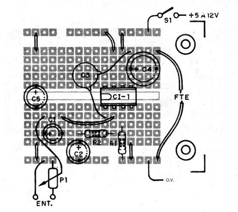
Figure 8 shows the arrangement of the components of this amplifier on a universal printed-circuit board.
For increasing bass tones, we suggest using the following vanes for the oscillators to be applied:
C = 47 nF and 2C = 100 nF
C = 68 nF and 2C = 120 nF
C = 82 nF and 2C = 150 nF
In order to improve the bass response when using these new oscillators, we suggest increasing the value of C4 in the amplifier to 1000 uF.
TESTING AND USE
To test the device, simply connect its power supply and initially adjust all the trimpots so that no continuous oscillations occur. Then, by quickly touching each sensor, adjust the corresponding trimpots to obtain the damped oscillations that characterize bongos.
The connected amplifier should have its volume adjusted appropriately and, if hum is detected, the wire shielding should be checked. The buzzing sound produced by touching the device can be eliminated by using electrical contacts instead of finger contact.
Light-action push-button switches and even reed switches can be used, although in the latter case the activation would be done by the proximity of small magnets.
The other pole of these switches can be connected to the positive power supply.
BILL OF MATERIALS (BOM)
a) Oscillators
Q1 to Q4 - BC548 or equivalent general-purpose NPN transistors
P1 to P4 - 22kΩ trimpots
S1 – On-Off switch
B1 - 9 or 12 V - battery or power supply
R1 to R4 – 82kΩ resistors (gray, red, orange)
R5 to R8 – 10kΩ resistors (brown, black, orange)
R9 to R16 – 47kΩ resistors (yellow, violet, orange)
R17 to R20 - 4.7kΩ resistors (yellow, violet, red)
C1, C7, C8 – 10nF ceramic or polyester capacitors
C2, C11, C12 – 22nF ceramic or polyester capacitors
C3 – 33nF ceramic or polyester capacitor
C4 – 47nF ceramic or polyester capacitor
C5, C6 - 4n7 - ceramic or polyester capacitors
C9, C10 – 15 nF - ceramic or polyester capacitors
C13 – 10 uF - electrolytic capacitor
C14 – 47 uF - electrolytic capacitor
Miscellaneous: printed circuit board, mounting box, battery connector, wires, solder, etc.
b) Power Supply
IC-1 - 7812 - integrated circuit
D1, D2 - 1N4002 or equivalent silicon diodes
C1 – 1500 uF - electrolytic capacitor
T1 - transformer with primary winding according to the local mains voltage and secondary winding of 12 + 12 V or 15 + 15 V x 500 mA
S1 - simple switch
F1 - 500 mA fuse
Miscellaneous: terminal block, power cable, heatsink for the integrated circuit, fuse holder
c) Amplifier
C1-1 - TBA820M - integrated circuit
P1 – 10 kΩ - potentiometer
FTE - 4 or 8-ohm x 15cm speaker
R1 – 10 kΩ - resistor (brown, black, orange)
R2 – 33 ohms - resistor (orange, orange, black)
C1 – 10 uF - capacitor Electrolytic
C2, C5 – 100 uF - electrolytic capacitors
C3 – 220 pF - ceramic capacitor
C4 – 470 uF - electrolytic capacitor
Miscellaneous: printed circuit board, socket for the integrated circuit, knob for the potentiometer, wires, shielded wire, P2 plug, etc.


